
Blog
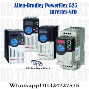
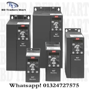
How an Inverter-VFD Works?
Dec
How an Inverter-VFD Works?
An Inverter-VFD is a motor control device that adjusts the speed of a standard AC induction motor by varying the frequency and voltage supplied to it. The terms Inverter, VFD (Variable Frequency Drive), VSD (Variable Speed Drive), and AFD (Adjustable Frequency Drive) are generally used interchangeably in industrial automation to describe the same device and function. A VFD operates in three main stages to convert fixed-frequency utility power into variable-frequency power suitable for controlling motor speed.
Variable Frequency Drive-VFD Operation:
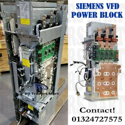
The Rectifier Stage
- Function: Converts the incoming AC (Alternating Current) power into DC (Direct Current) power.
- Components: Typically uses diodes or SCRs (Silicon Controlled Rectifiers) in a bridge configuration.
- Result: Creates a constant high-voltage DC bus.
The DC Bus (Intermediate Circuit)
- Function: Smooths out the pulsed DC voltage received from the rectifier.
- Components: Uses large capacitors to filter the voltage ripple, creating a stable DC voltage source.
The Inverter Stage
- Function: Converts the stable DC power back into AC power with a variable frequency and voltage.
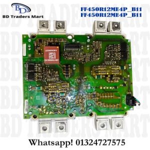
- Components: Uses high-speed power transistors, most commonly IGBTs (Insulated Gate Bi-polar Transistors).
- PWM: The IGBTs rapidly switch the DC voltage ON and OFF to synthesize a simulated AC sine wave using a technique called Pulse Width Modulation (PWM)
Key Benefits in Industrial Applications
- Energy Savings: This is the primary benefit, especially for pump and fan loads. The cube of the speed (Power reducing the speed by just 20% can cut energy usage by nearly 50%)
- Process Control: Allows precise control over the speed, torque, and position of the motor, improving product quality and process efficiency in applications like conveyors and mixers.
- Soft Starting: Reduces the large inrush current and mechanical shock that occurs when starting a motor directly across the line, extending the life of the motor and machinery
3 Stages of Inverter Operation
The Rectifier Stage (AC to DC)
- Components: Typically uses a bridge rectifier circuit consisting of diodes or SCRs (Silicon Controlled Rectifiers)
- Result: The sinusoidal AC input is converted into a pulsating DC voltage
The DC Link / Bus (Filtering and Storage)
- Components: The capacitors (and sometimes inductors) to smooth out the ripples in the DC voltage.
- Function: This stage acts as an energy reservoir, storing the DC power and providing a stable, constant DC voltage source for the next stage
The Inverter Stage (DC to Variable AC)
- Components: Uses high-speed electronic switches, most commonly IGBTs (Insulated Gate Bipolar Transistors)
- Method: The IGBTs switch the DC voltage ON and OFF thousands of times per second in a technique called Pulse Width Modulation (PWM)
Control Principle (Speed Regulation)
By adjusting the V/Hz ratio, the VFD achieves smooth starting (soft start), controlled acceleration/deceleration, and precise speed regulation, leading to significant energy savings, especially in pump and fan applications.

How to Working of Rectifier in VFD?
The Rectifier is the crucial first stage in a VFD (Variable Frequency Drive). Its primary job is to convert the incoming, fixed-frequency AC (Alternating Current) utility power into DC (Direct Current) power that can be used by the inverter stage. This process is essential because the inverter stage requires a stable DC voltage source to create the variable AC voltage and frequency needed to control the motor speed.
How work control unit in the Inverter?
The Control Unit (CU) is the brain of an Inverter (VFD – Variable Frequency Drive). It is a microprocessor-based system responsible for executing the control algorithms. That govern motor’s operation, ensuring the motor runs at the precise speed, torque, and efficiency demanded by the application. Its work can be broken down into three main, interconnected tasks of Command Interpretation, Control Loop Execution, and IGBT Switching Control.